Fire Suppression System Diagram
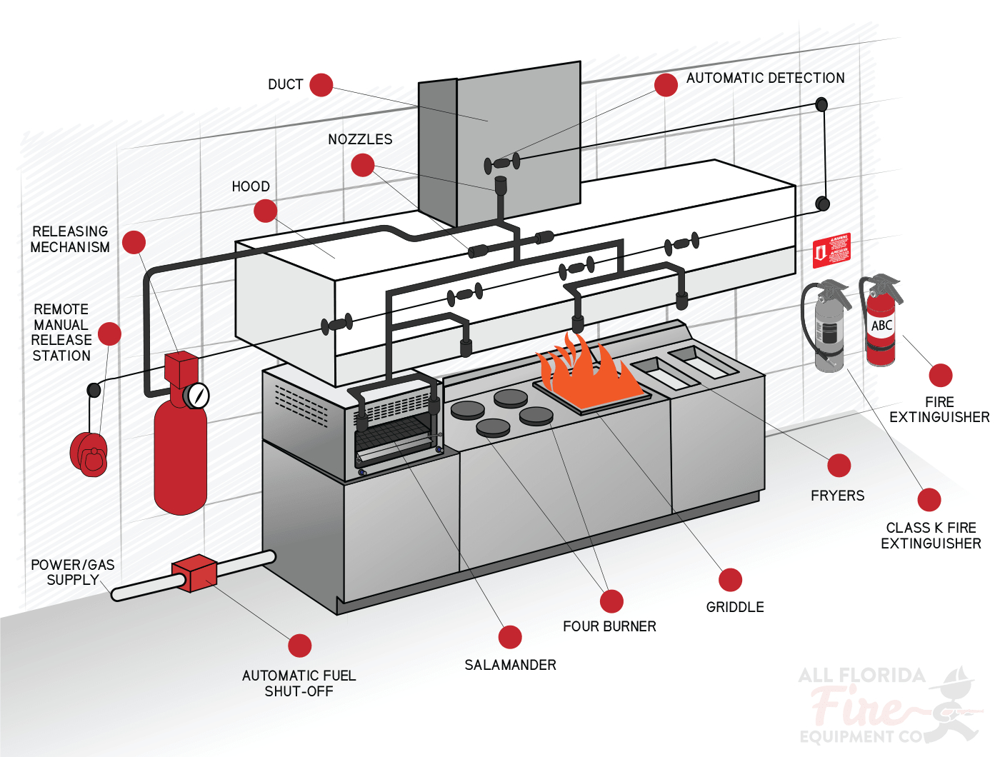
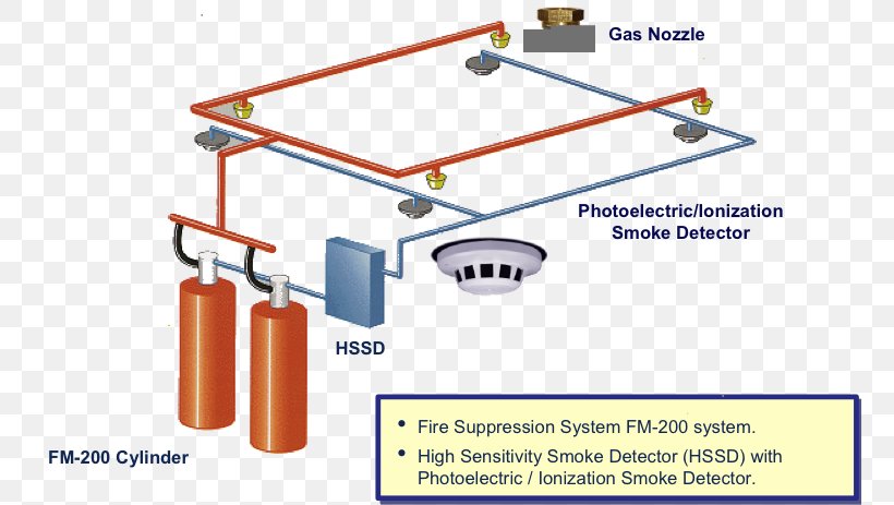
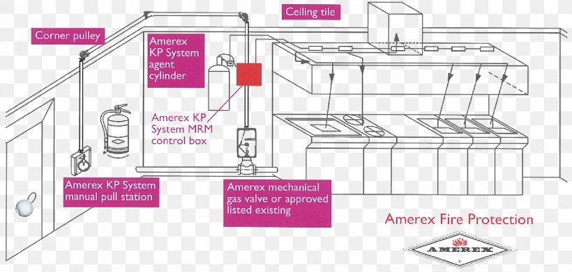
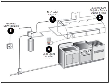
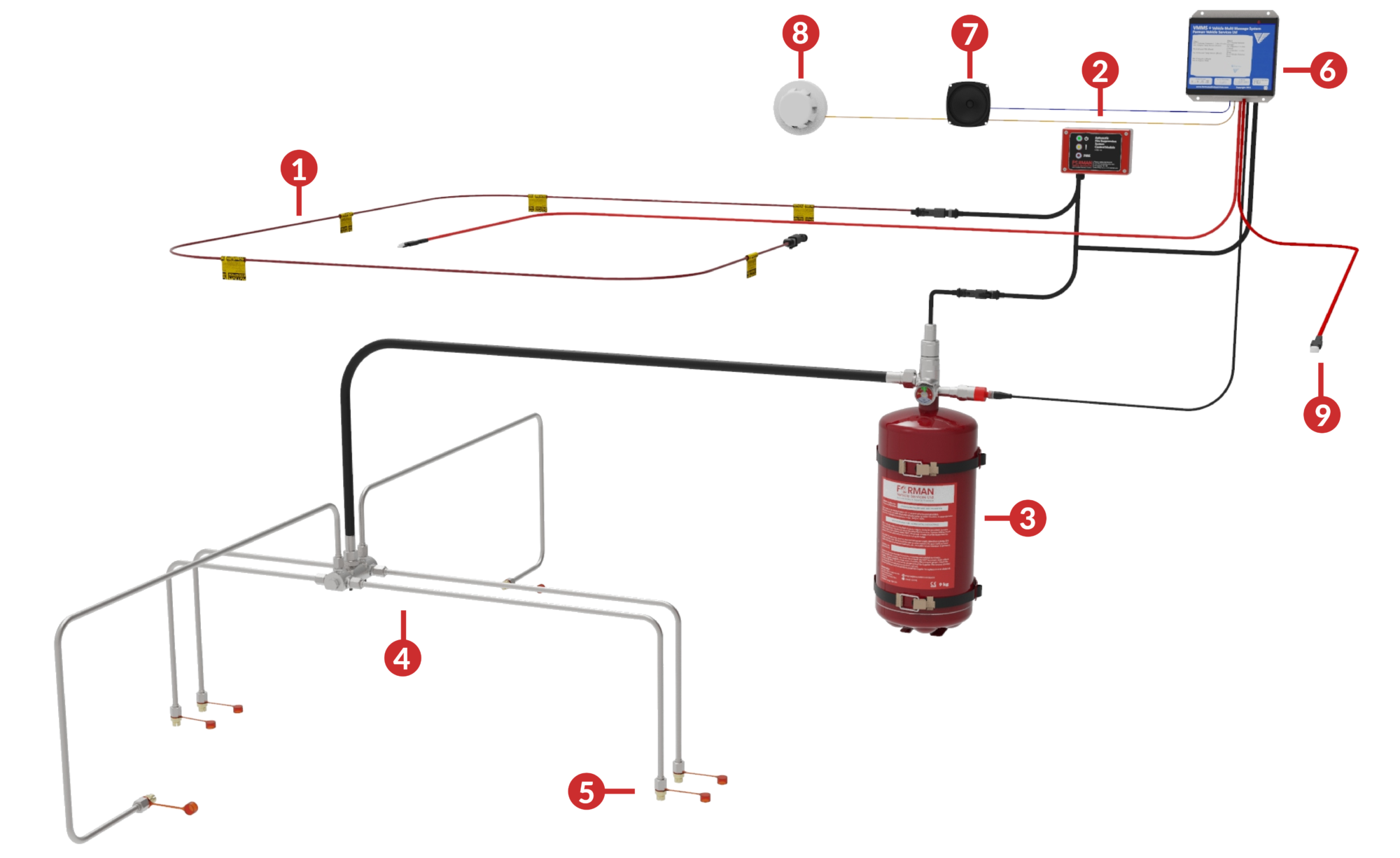
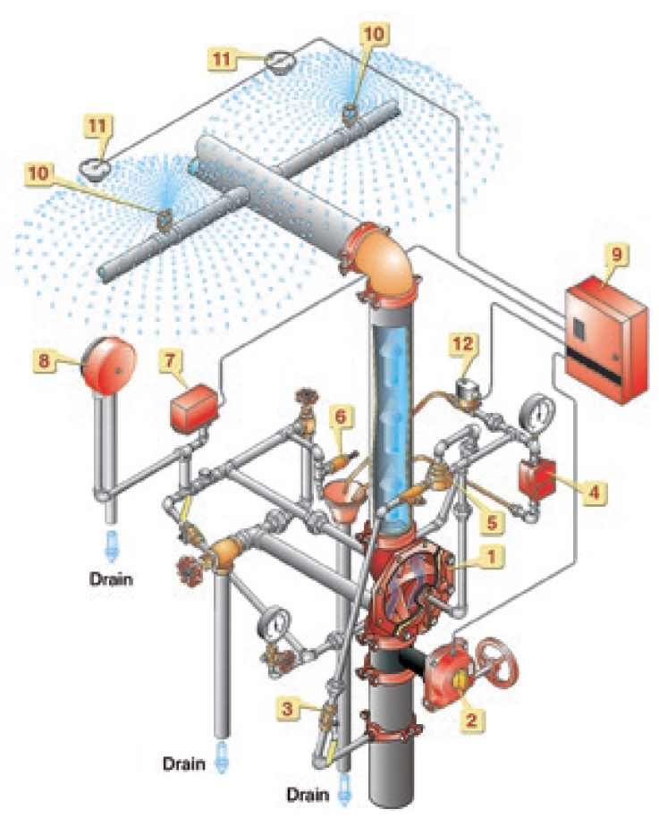
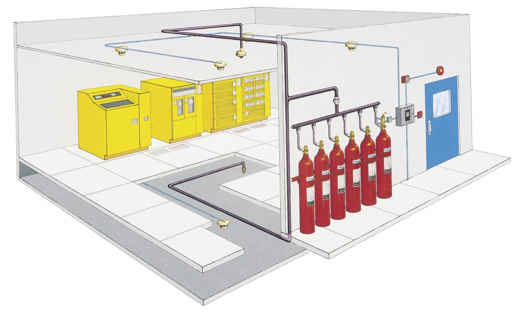
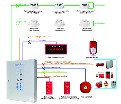
Fire suppression system diagram. Diagram schematic diagram of Complete Fire Extinguishing System April 10 2018 Aerosol dry chemical powder HFC-227ea carbon dioxide IG541 IG55 IG01 foam equipment can be part of a fire extinguishing system but not a complete system a complete fire suppression system is not only include fire extinguishing equipment but also include fire alarm systems. The ansul r 102 restaurant fire suppression system is developed and tested to provide fire protection for restaurant cooking appliances hoods and ducts. Label System Wiring Diagram Remote Release R Ansul.
Fire System Micro Switch from the ANSUL or PYROCHEM Fire Suppression System connect wires. Schematic Diagram Of Fire Protection System. 58 Fire Extinguishing System VSH1230 F_012319 Rev 191 en-US.
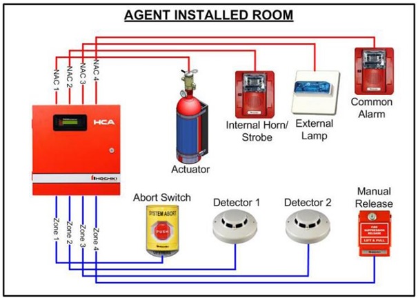
ANSUL R-102 Fire Suppression System Product Overview Rev. From an The suppression tech will also have the wiring diagram. A control unit receives inputs from all fire detection devices automatic or manual activating the corresponding notification systems.
A fire alarm system monitors the building for the presence of fire producing audible and visual signals if fire is detected. It is the most efficient solution to control the risk of fire which is inherent to all professional kitchens without putting customers or staff in danger. Lets discus each one in details as follow.
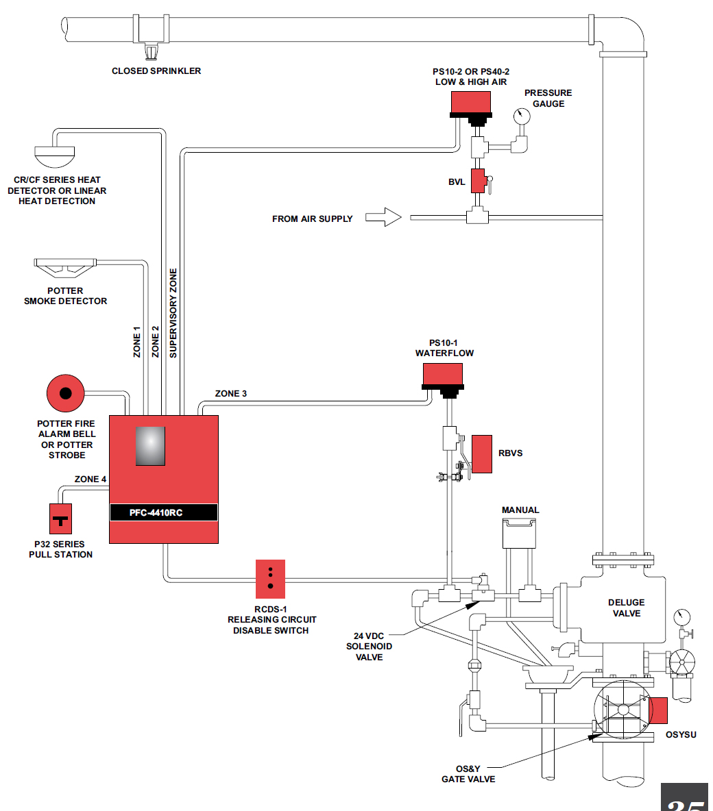
It reacts rapidly and automatically to suppress the fire. Pull Station Handle Located by an exit for safety. Fire protection system operation schematic diagram of the fighting crp extinguishing block widar deluge and pre action systems fox firewater an overview how high pressure water mist alarm circuit.
The Ansul R Restaurant Fire Suppression System is an automatic pre-engineered fire suppression system The R system. Conventional Fire Alarm System. Ansul r 102 wiring diagram facbooik for ansul system wiring diagram image size 720 x 917 px and to view image details please click the image.
The system provides automatic actuation. Gas valve must be wired so when exhaust fan is off gas is off-any wiring diagram.
Schematic Diagram Of Fire Protection System.
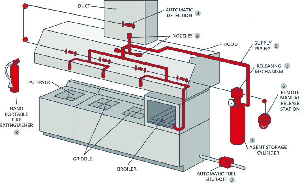
The system and components shall be a Kidde Fire Suppression System as manufactured by KIDDE FIRE SYSTEMS INC 400 Main Street Ashland MA. Ansul R-102 is a liquid and chemical fire suppression system. The as-builts are to include the following as a minimum. The designer is responsible for checking the accuracy of as-built drawing prepared by the Fire Suppression contractor. ANSUL R-102 Fire Suppression System Product Overview Rev. Pull Station Handle Located by an exit for safety. For appliance shutdown requirements refer to the current ver-sion of NFPA 17A Standard For Wet Chemical Extinguishing. Typical Fire Suppression System Diagram 1. Conventional Fire Alarm System.
The field electrician is required to wire the following. Provide a complete PIRANHA automatic water-assisted wet chemical fire suppression system as specified herewithin and as shown on the design drawings. Wireless Fire Alarm System. For appliance shutdown requirements refer to the current ver-sion of NFPA 17A Standard For Wet Chemical Extinguishing. Addressable Fire Alarm System. Or it can be actuated manually through a remote manual pull station. Ansul R-102 is a liquid and chemical fire suppression system.














Post a Comment for "Fire Suppression System Diagram"